Today is my first time doing a blog in my life. I hope everything will be fine. So, I would like to share with you all about my electronic system class.
Electronic is a very interesting subject. Almost all the gadget we use come from electronic. But, did you know what the component inside the electronic gadget? How they work and how the design? So, in my blog you all will learn about the electronic.
My first topic in the class (Basic Electronic & Testing Equipment)
Dear all, last week I learn this topic in the class.In this topic I learn about all the basic component in electronic. Example like resistor, capacitor, LED(light emitting diode), transistor, IC (integrated cicuit) and so on.
Mr Redzuan also teach us how to calculate the resistor using the color band. Below is the color code for the resistor.

Do you know how to remember this color code? For the first time very difficult to get it.
Here is the tips to remember it
Big Brown Rabbits Often Yield Great Big Vocal Groans When Gingerly Slapped.
You all also freely to create the mnemonic by yourself. As long you can easily remember it.
Beside that, I also learn how to read the capacitor color.As you all know, capacitor function to store a charge. Here also I attach the table for capacitor color code.
.jpg)
Transistor
Transistor is a semiconductor device that can be use to amplify and act as a switch.
Workshop(PCB Design & Simulation)
This week in Electronic system engineering subject we learn how to design PCB using multisim & ultiboard. This software is user friendly and easy for beginner to study. In our lab, we lack of PC and need to share among others to using this software. I have to share with 3 of my friend to design the PCB. Even thought we have to share, we still can understand how the software work. To design the PCB we have many software. there are OrCAD,CADSTAR,EAGLE PCB, and so on.
In the lab session, Mr Redzuan give us a labsheet to practice the PCB design using mutisim. Below is the picture of circuit that we need to draw in multisim.

Before this I have experience using EAGLE software to draw a circuit, but I found out the mutisim much more easier to draw.So, I hope my friend happily enjoy to use this software to design the circuit.
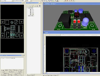
The best thing using this software, we can simulate a 3D view. We can see the component in 3D and can rotate the movement. For your information, make sure during draw the circuit we use the real component to avoid the problem during transfer to the ultiboard. Real component usually appear in blue color and the virtual component in black color. Make sure all the connection connect properly to avoid any error. Below is the complete circuit we draw using multisim.

After we complete draw the circuit using multisim, we transfer to ultiboard. Then, we can view complete 3D version of PCB board. Below is the sample of picture I take from my friend.
Very nice. Thats all we learn in this week lab. Multisim is very awesome, we can use it for next project. I hope you all enjoy reading my blog. Put any comment for further improvement in future. Will be continue in next topic. Bye.
No comments:
Post a Comment